


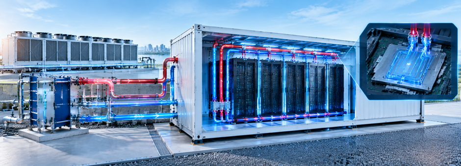
The fastest way to cut energy in containerized data center cooling is to delete the compressor, not tune it. For GPU modules above roughly 20 kW per rack, a warm-water direct-to-chip loop running at 40 to 45 degrees Celsius can reject heat through a dry cooler alone, holding PUE near 1.1 to 1.2 without a chilled-water plant or facility piping. Supply temperature, CDU sizing, and condensation control decide whether that chiller-free design works in the field.
Why Does Containerized Data Center Cooling Hit a Wall Around 20 kW per Rack?
Air is a poor heat-transfer medium, and a steel shipping box leaves little room to compensate with volume. In containerized data center cooling, that volume constraint is tighter than in any conventional hall. Conventional air cooling works reliably up to about 15 kW per rack and reaches a practical ceiling near 20 to 25 kW once fan energy and hot spots are accounted for. JLL reports that air stays efficient only to roughly 20 kW, after which active rear-door heat exchangers and then direct liquid cooling take over.
The density gap in containerized data center cooling is widening fast. McKinsey notes AI workloads now demand 60 to 120 kW per rack, and Nvidia’s GB300 racks peak near 163 kW. A module designed for 10 kW airflow cannot cool that hardware by adding fans; static pressure, noise, and fan energy become prohibitive. At dense air sites, fans can consume 15 to 25 percent of total energy.
This is why containerized data center cooling has bifurcated. Low-density edge and storage modules still use direct-expansion or evaporative air systems, while GPU and HPC modules ship with liquid loops as the primary heat path for containerized data center cooling. Dell’Oro Group expects leading-edge GPU thermal design power to exceed 4,000 W per chip by 2029, up from roughly 700 to 1,000 W today, locking in liquid as a structural requirement rather than an option.
What Makes Warm-Water Direct-to-Chip the Default for AI Modules?
Direct-to-chip cooling mounts cold plates on the GPU and CPU, moving heat at its source. This is the architecture most new containerized data center cooling designs now adopt for AI. Liquid removes heat far more effectively than air, which is why a compact module can hold racks that would otherwise require a much larger air-cooled hall. In a sealed, factory-built box, this matters twice: it shrinks the airflow needed and it concentrates heat rejection into a compact external dry cooler.
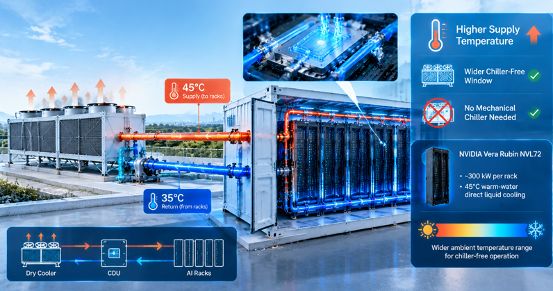
Warm-water operation is the specific lever that removes the chiller from containerized data center cooling. Mechanical chillers exist mainly to produce cold water, often 7 to 15 degrees Celsius. If the chips accept 40 to 45 degree supply water, ambient air can cool that loop directly for most or all of the year, depending on climate. ASHRAE TC 9.9 defines liquid-cooling equipment classes from W17 upward, with the W32, W40, and W45 classes describing the warm-water regimes that modern servers increasingly support.
The efficiency result is measurable. The Uptime Institute’s 2025 survey puts air-cooled facilities at PUE 1.55 to 1.67, while direct-to-chip systems reach 1.10 to 1.25. Dell’Oro reports the liquid-cooling market nearly doubled in 2025 to about 3 billion dollars and should approach 7 billion by 2029. In containerized data center cooling, that efficiency arrives with no central plant.
Vendor products confirm the trajectory. Delta’s AI Containerized Data Center fits up to 60 kW per rack in a standard 20-foot ISO box, uses a liquid-to-air system with no facility water piping, and achieves PUE below 1.19. That combination, high density plus dry rejection plus a parking-space footprint, is the template warm-water containerized data center cooling now follows.
Which Supply Temperature Lets a Module Reject Heat Without a Chiller?
The decisive number in containerized data center cooling is the coolant supply temperature at the cold plate, because it sets the minimum ambient temperature at which a dry cooler can keep up. A higher supply temperature widens the chiller-free window. Nvidia’s Vera Rubin NVL72 roadmap targets roughly 300 kW per rack with 45 degree warm-water direct liquid cooling precisely so dry coolers can reject heat without mechanical chillers.
The arithmetic is a temperature approach, not a guess. A dry cooler needs coolant entering it to stay above ambient by a finite approach, typically 8 to 15 degrees under load. With 40 to 45 degree supply water, a module runs compressor-free in many temperate climates for thousands of hours a year, using a small trim cooler only at the hottest peaks. This is how containerized data center cooling stays chiller-free; colder water shrinks the window and brings the chiller back.
Pushing supply water too high carries its own penalty. Chip temperatures must stay below the manufacturer’s throttle point, and a small temperature rise across the cold plate leaves little margin. Field designs for earlier GPU generations commonly hold supply water between 25 and 35 degrees to balance throttling against condensation. The practical move is to match the supply set point to the exact GPU specification, then add only as much trim cooling as local weather data requires.
How Should the CDU, Manifold, and Dry Cooler Be Sized Inside a Container?
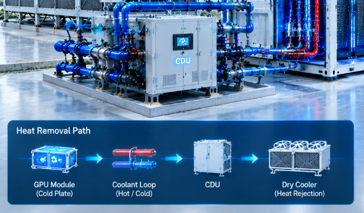
Sizing containerized data center cooling should start from the chip roadmap, not the current load, because every GPU generation raises heat density. The coolant distribution unit, or CDU, transfers heat from the server secondary loop to the facility-side loop and provides pumping, filtration, and pressure control. Row- or rack-level CDUs in the 1 MW class can serve a dozen or more high-density racks while keeping a standard footprint.
Plan the loop for the next verified platform, then add CDU capacity in factory-tested increments. A module fully plumbed for future pumps avoids cutting into a sealed box on site. The dry cooler is sized from total heat rejection plus the approach at the local summer peak, not nameplate IT power alone; residual heat the liquid does not capture still leaves through air.
Redundancy in containerized data center cooling deserves explicit attention because a stopped pump interrupts cooling within minutes. N+1 pumps and CDUs, isolation valves at each rack, and quick-disconnect fittings with locking tabs let a single rack be serviced without draining the module. This layered capacity is the difference between a warm-water system that stays chiller-free and one that trips into backup refrigeration under a component failure.
Where Does Condensation and Leak Risk Enter the Loop?
Warm-water loops are safer than chilled loops on condensation, but they are not immune, and condensation is one of the most underestimated risks in containerized data center cooling. Condensation forms when a surface drops below the surrounding dew point, so the coldest point in the system, usually the supply manifold or cold plate inlet, must stay above dew point with margin. Raising supply temperature toward 40 degrees helps, but humid outdoor air leaking into a cooled enclosure can still push dew point upward.
Holding dew point down starts with enclosure integrity. A factory-pressure-tested container with sealed cable entries, rack gaps, and door gaskets keeps humid ambient air out and protects efficiency; even small air leaks can cut cooling effectiveness by several percent. Dew-point sensors at the cold-rail and manifold, interlocked to raise supply temperature or reduce cooling, provide an active backstop before moisture appears.
Leak control is hydraulic and electrical at once. Deionized water or approved coolant with controlled conductivity reduces short-circuit risk, while leak-sensing cables or ribbons under manifolds and CDUs catch drips early. Valves at each rack inlet isolate a single failing connection. Specifying these sensors and valves before the module leaves the factory is far cheaper than retrofitting them into a sealed, powered box.
Can Air and Liquid Share the Same Container?
Most AI modules are hybrid, and in containerized data center cooling the split should be deliberate rather than accidental. Liquid captures the concentrated GPU and CPU heat, commonly the large majority of the load, while air handles networking gear, storage, power electronics, and the residual heat the cold plates do not capture. Keeping a modest air path also provides redundancy if the liquid loop degrades.
The benefit is matching cooling investment to heat. Dense GPU racks get cold plates; low-density support racks get air, avoiding over-provisioning liquid. Operators can then raise the air-side set point slightly, trimming fan and refrigeration energy in containerized data center cooling.
The risk is an unmeasured residual. If the stated liquid capture ratio is optimistic, the air system must reject more heat than designed, and hot spots return near switches and rear cabling. The capture ratio should therefore be verified against the real server configuration, not assumed from a vendor headline, and the air path sized for the actual remainder with a defined margin.
What Should Acceptance Testing Measure Before a GPU Module Leaves the Factory?
Because a container ships as a finished product, the factory acceptance test is the last cheap place to catch errors in containerized data center cooling. The test should measure the entire heat-removal path, from cold plate to dry cooler, under a load that represents the deployed GPU density rather than a fraction of it. Recording supply and return temperatures, flow, pressure drop, and CDU power at full load exposes undersized pumps and fouled exchangers early.
Three measurements carry the most weight. First, the achieved supply temperature and approach to ambient confirm whether the module truly runs chiller-free at the design climate. Second, per-rack flow and delta-T confirm balanced distribution and the real liquid capture ratio. Third, a forced pump or CDU failover proves the redundancy logic holds temperature within limits during the switch.
Water and energy data belong in the same test. Closed-loop liquid systems can run below 0.2 liters per kilowatt-hour according to HyperFRAME Research, far below evaporative designs, and that figure should be checked, not promised. Logging total input, IT load, and cooling power turns the snapshot into an operating baseline.
Is Containerized Data Center Cooling Ready for the Next GPU Generation?
The direction is settled, but readiness is a design choice. AI racks are moving from 120 to 163 kW toward 300 kW and higher, and Nvidia’s warm-water roadmap makes chiller-free rejection the expected architecture rather than an experiment. AFCOM reported in 2025 that only about 19 percent of data centers had implemented liquid cooling, though 36 percent planned to adopt it within two years, so capacity and skill are still catching up.
Building the loop for tomorrow’s chip is the single most important decision. A module sized for today’s 30 kW load becomes a stranded box when 4,000 W accelerators arrive; a module with warm-water manifolds, incremental CDU capacity, and a correctly sized dry cooler absorbs that generation without a compressor. Google has shown that machine-learning control can cut cooling energy by about 40 percent, and that logic now ships inside modular control platforms.
For planners evaluating containerized data center cooling, the practical answer is to specify warm-water direct-to-chip from day one, verify the chiller-free window against local weather, and require full-load factory testing of the complete loop. If you treat the dry cooler as optional rather than the primary rejection path, the compressor quietly returns. Done correctly, the compressor disappears from the design, and with it a large share of both energy cost and site infrastructure.

发表回复